Thermal Inspection Robots: Workflow Fit, Limits and Validation
A measurement-first framework for repeatable robot thermal inspection, covering read-point geometry, emissivity, validation, uncertainty and escalation.

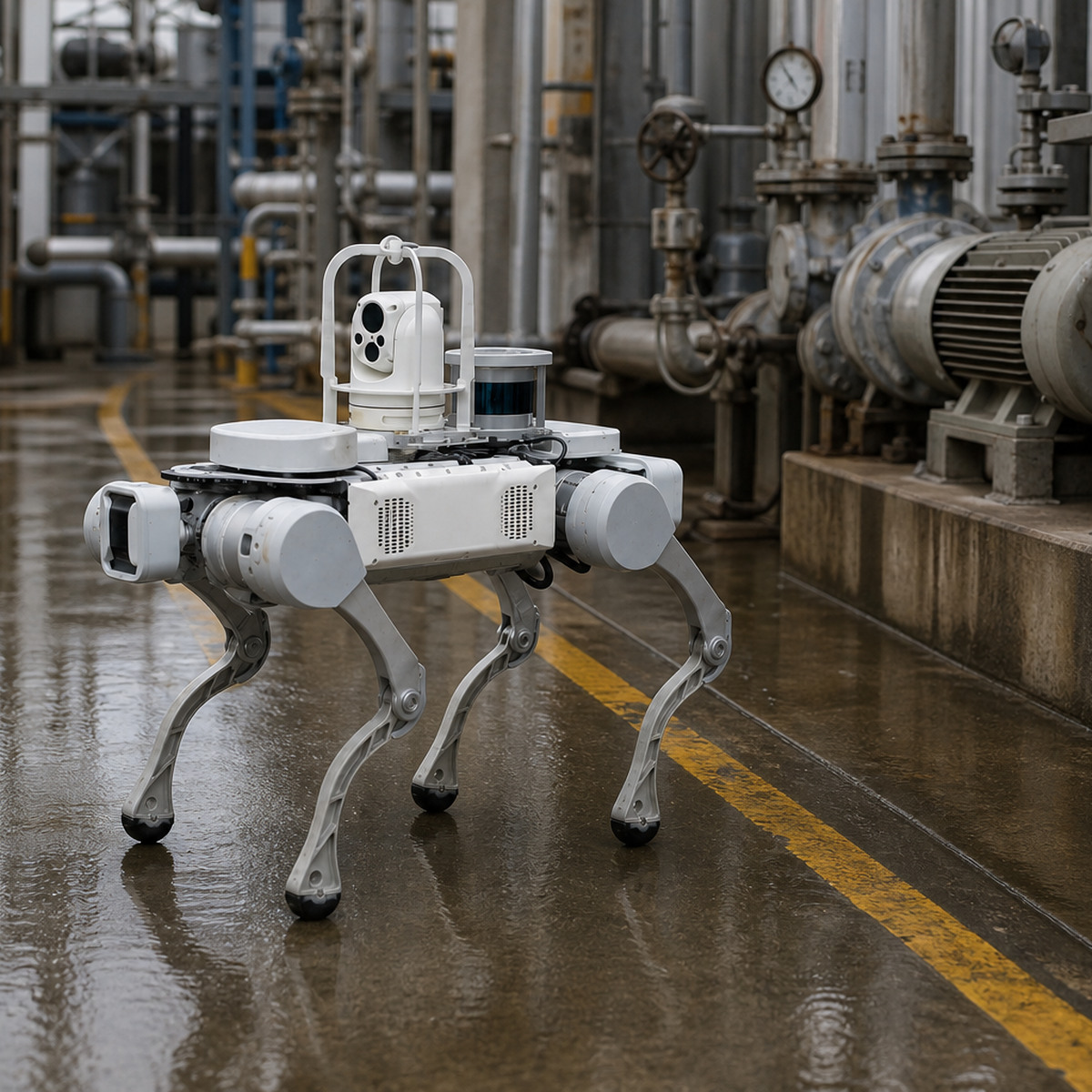
A thermal inspection robot is useful when it can collect comparable thermal evidence at defined assets and read points—not merely produce colorful infrared images. The buyer decision is therefore whether a mobile thermal workflow can repeat the camera position, measurement conditions, data checks and escalation path closely enough to support a maintenance decision.
Start with the measurand and decision. Identify the component to observe, the condition that matters, the comparison or threshold used by the reliability team, and the action that follows. Then evaluate the industrial inspection robotics solution as a complete measurement system: mobility, camera, mounting, route, environment, data handling and human review.

Define the inspection before choosing the camera
“Find hot spots” is not an acceptance requirement. A useful thermal task identifies the asset and component, expected operating state, field of view, surface characteristics, camera distance and angle, environmental constraints, comparison method and evidence record. A motor bearing, electrical connection and refractory surface may all be inspected thermally, but they do not share the same interpretation.
The U.S. Department of Energy’s operations and maintenance guide describes infrared applications across electrical connections, motors, gearboxes, conveyor rollers, refractory and distribution systems. It also shows the value of comparing thermal patterns and trending repeat observations. That is a reason to design repeatable observations; it is not evidence that every temperature difference proves a fault.
Control the variables that change a reading
FLIR’s technical guidance states that thermal-camera measurements show surface temperature and can be affected by distance, ambient temperature and emissivity. Highly polished, low-emissivity metal can reflect radiation from other objects, so the apparent temperature may not be the target’s actual temperature. A robot does not remove those physics.
Specify each read point with the variables the inspection method requires:
- Target and region of interest: identify the exact component, not only the machine.
- Operating state: record load, process state and relevant comparison assets.
- Pose: define permitted distance, view angle, height and field of view.
- Camera setup: record lens, focus, range, emissivity setting and reflected-temperature treatment.
- Environment: note ambient conditions, nearby heat sources, steam, dust, wind and direct reflections.
- Quality gate: classify each acquisition as valid, uncertain or invalid before applying an alarm rule.
If the target cannot be measured reliably from the planned route, change the method, target preparation, sensor position or decision boundary. Do not compensate for a weak acquisition by making the analytics sound more certain.
Separate anomaly screening from temperature measurement
A thermal image can support different decisions. One workflow may screen for a pattern that differs from comparable equipment. Another may require a defensible surface-temperature estimate. The second demands stricter control of emissivity, reflected temperature and geometry.
Define which level the robot is expected to provide:
- Presence check: confirm that an expected warm or cool region is visible.
- Comparative screening: compare similar components under comparable conditions.
- Trend monitoring: compare the same region over time with controlled acquisition.
- Quantitative measurement: use a reviewed thermography method with recorded correction factors and uncertainty.
These levels should not be blended in reporting. A screening exception is a request for review, not an automatic diagnosis.
Validate the robot, sensor and workflow in layers
Begin off-route. Verify asset identity, camera configuration, timestamp, data storage and image review using controlled targets. Then accept individual read points under representative operating conditions. Only after the readings are stable should the team validate route segments and complete missions.
For each read point, test expected variation: slightly different approach angles, ambient changes, reflective backgrounds, partial occlusion and normal equipment-state changes. Record whether the workflow reacquires the image, marks it uncertain, defers it or escalates to a person. The acceptance set should include both valid and intentionally invalid captures.
Evaluate four outcomes separately:
- the robot reached the correct read point;
- the camera captured an acceptable thermal record;
- the record was associated with the correct asset, time and configuration;
- the review and escalation process reached a documented disposition.
A completed route with unusable thermograms is not an inspection success. An accurate image that no one reviews is not an operating workflow.
Design thresholds around evidence quality
Alarm logic should account for measurement validity before comparing a value with a threshold. Useful states include normal, review, urgent review, invalid acquisition and sensor or route exception. Retain the original image, configured parameters, asset identity, read-point version and review decision so that a later investigator can understand why an alert was generated.
Use human review where the consequence of a false negative or false positive is material. A qualified thermography or reliability reviewer should approve the target, acquisition method, comparison basis and escalation rule. The automation can prioritize consistent evidence; it should not conceal uncertainty.
Know when thermal inspection is a poor fit
Pause or redesign the workflow when the target cannot be viewed safely, surfaces are highly reflective without a valid compensation method, operating states cannot be compared, the route cannot reproduce the required pose, the camera cannot meet the needed range or resolution, or the site cannot support calibration, cleaning and review ownership.
Thermal inspection also does not replace electrical safety procedures, isolation rules, specialist testing or a root-cause investigation. The robot changes how evidence may be collected; it does not change the organization’s responsibility to define and control the inspection.
Use a practical readiness checklist
- List assets, components, decisions and consequences.
- Choose screening, comparison, trending or quantitative measurement as the task level.
- Define read-point geometry and operating conditions.
- Document emissivity and reflected-temperature treatment where relevant.
- Specify valid, uncertain and invalid acquisition rules.
- Test route repeatability and expected environmental variation.
- Assign review, alarm, maintenance, calibration and change-control owners.
Use the current industrial inspection deployment guide to assess access, network and operating constraints before committing to a pilot.
Related planning: Translate the measurement conditions into versioned read points with the autonomous inspection route-design guide.
Sources and scope
This article combines primary and first-party technical sources with an editorial workflow framework. It does not provide thermography certification, electrical-safety advice, a product performance claim or evidence of a Warpify customer deployment.
- How Does Emissivity Affect Thermal Imaging? — FLIR
- Using a Thermal Camera: Measurements — FLIR technical documentation
- Operations & Maintenance Best Practices Guide: Release 3.0 — U.S. Department of Energy
Take the next step
Bring a current asset list, manual thermography route and sample records to a site-specific review: request an industrial inspection assessment.

Iven Wang
Iven Wang is the Co-Founder of Warpify Robotics, specializing in the commercialization and deployment of robotic solutions. With a background in electrical engineering and product management, he works with manufacturers, integrators, and enterprise clients across industrial inspection, security, logistics, and Robotics-as-a-Service.
Subscribe to our newsletter today
Get practical robotics deployment insights, case studies, and planning guidance from Warpify Robotics.